I recommend that you read this document completely before doing anything.
Tools you will need:
Remove the screws holding the cover on. Note that the screws for the sides are different than the screws for the back - set them aside and remember which are which.
Remove the cover by lifting it at the back and then gently pull away from the front panel.
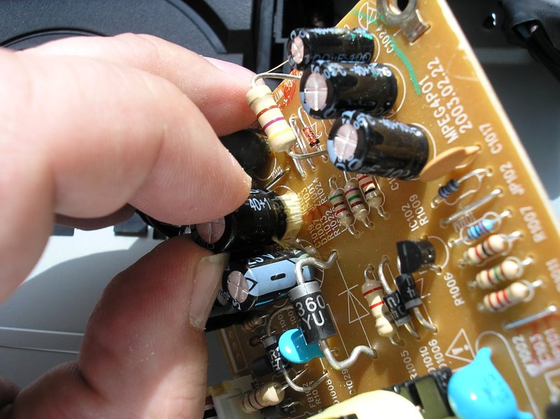
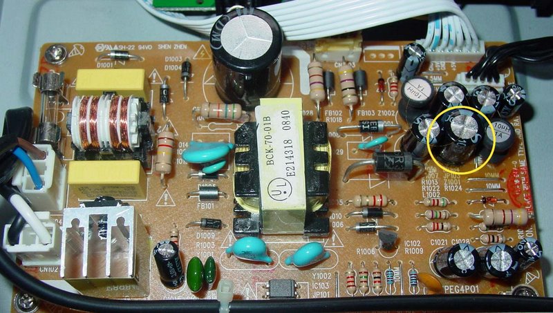
The capacitor to be replaced is circled on the picture below (click on the pictures for larger images). The original part is 1,000uF @ 16v but I recommend that it be replaced by a 1,000uF @ 25v or 35v or more.
IMPORTANT: Note the orientation of the white stripe on the capacitor - it is towards the top of the picture! You must orient the replacement capacitor the same way - with the stripe in the same place.
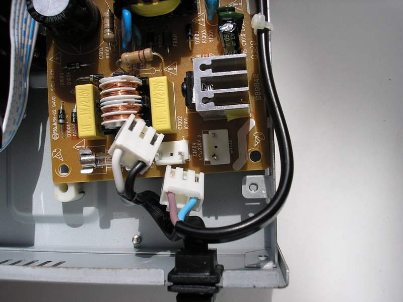
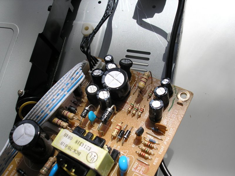
Unplug the power cord and the power switch from the power supply board: the two white plugs shown in the photo below. Note which one goes where! Remove the four screws holding the power supply to the chassis.
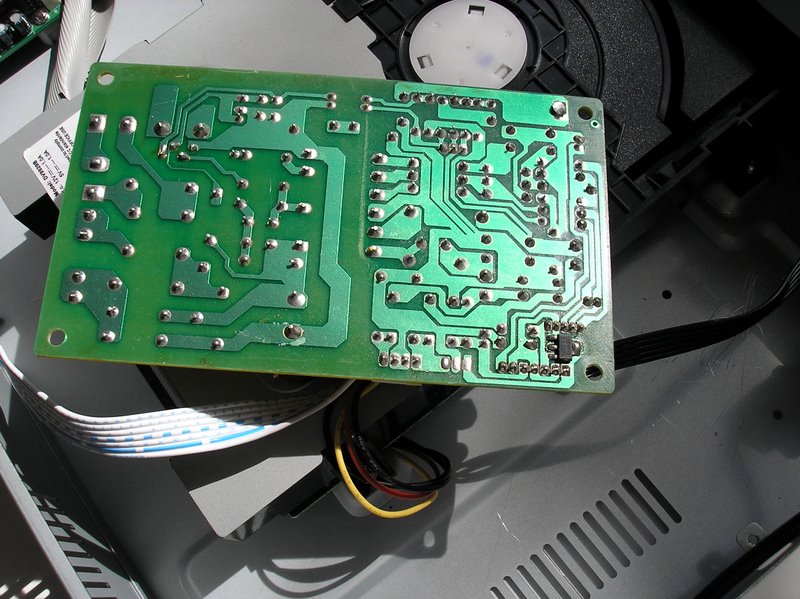
Gently flip the power supply board upside-down, laying it on top of the
loader as shown below.
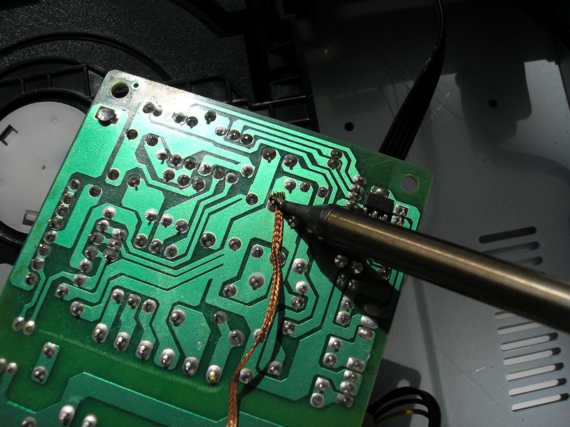
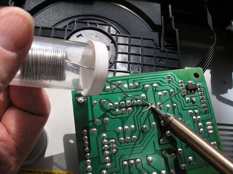
Plug in your soldering iron and wait until it is hot enough to quickly
melt solder when touched to the tip. Lay the desoldering
braid on top of one of the solder joints holding the capacitor to the
circuit board. Press a fresh end of the desoldering braid to the joint
with
the tip of the
soldering iron as shown in the picture below. When the braid get hot
enough, the solder below it will melt and be absorbed by the desoldering
braid.
As the desoldering braid becomes engorged with solder, feed it forward so
that a
fresh section lays over the remaining solder and repeat until all of the
solder has been removed and the capacitor lead is free. Clip off the
used section of the desoldering braid and repeat for the
second connection holding the
capacitor.
Remove the capacitor from the circuit board by lifting it away. Note:
there may also be adhesive holding the capacitor to the board as shown in
the picture below.
Orient the replacement capacitor with the white stripe in the correct
position and insert the leads into the two holes in the circuit board.
Gently press the capacitor to seat it as low to the circuit board as
possible but don't force it. Slightly different spacing of the capacitor
leads may not allow it to sit directly on the circuit board
like the original. While holding it in place, bend the leads back at a
slight angle, as shown in the picture below. This will hold the capacitor
in place. Touch the tip of your soldering iron to one of the leads
just where it emerges from the circuit board so that you are heating
both the lead and the printed copper foil on the circuit board at the same
time. Touch the solder to the joint, not the soldering iron and, as it
melts, feed it just a little more so that the total amount of
solder is similar
in size to the other connections on the circuit board. Remove the
soldering iron as soon as possible so that the capacitor and the circuit
board are not damaged. Repeat for the second lead. Do not allow the
solder to splash or bridge from one connection to the other! Remove any
excess solder. When the solder has cooled, clip the excess capacitor leads
with a pair of diagonal cutters or,
even, a nail clipper. Make sure the clippings do not fall into the
circuit board or the player.
The image below shows the new capacitor in place. It is necessary that
the capacitor be secured so that it cannot vibrate. This can be done by
using a small amount of contact cement or silicon sealent around the base
of the capacitor. It is also possible to use a couple of tiny drops of
"super glue" to fasten the capacitor to the adjoining parts which surround
the new
capacitor.
Reversing your steps, carefully reassemble the unit. Make sure that
there are no bits of wire, solder, etc. in the unit before you
close it. You should turn the player upside down and shake it before
putting the cover back on.
That's it! Questions? Comments? Suggestions? Contact CAVU